How to disable lockout chip
May 25, 2013 17:58:58 GMT -6
Post by gamernes on May 25, 2013 17:58:58 GMT -6
I figured I would take apart my NES with the disabled lockout chip so the information on how to do it is here. First off you will need a #2 phillips head screwdriver. Remove the 6 screws in the recessed holes that hold the outer casing together.
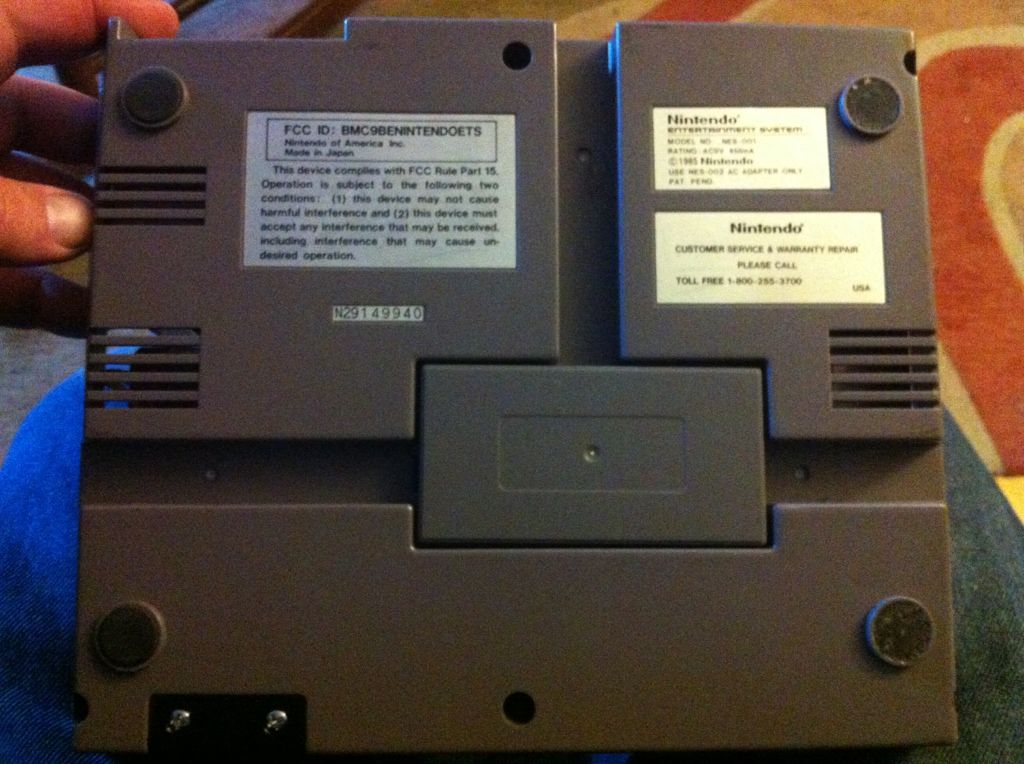
Lift the bottom half off and set the top half aside. Turn the buttom half over and dont lose the screws. Next remove the screws from around the RF shield. This will reveal the game tray.
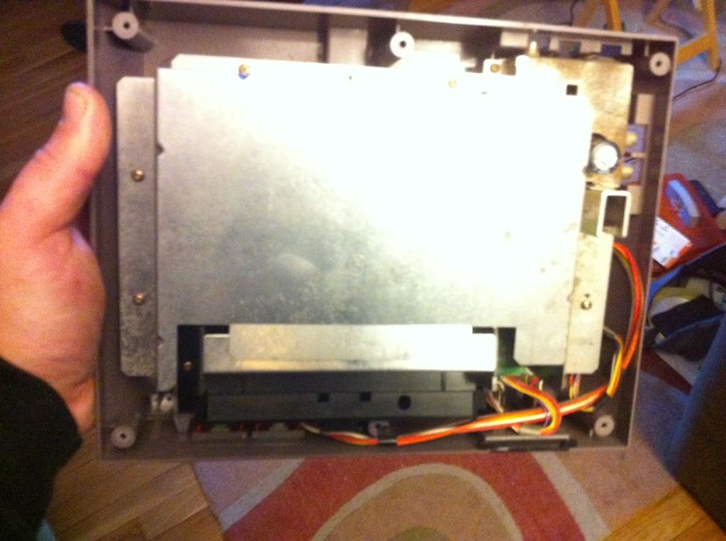
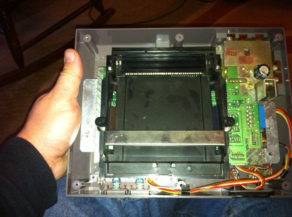
I always remove the tray to make it easier for myself. Note that the two rear screws that hold the tray in are longer than all of the other screws that have been removed. Next remove the two screws in the corner where the a/c adaptor and rf switch plug in.
s1249.photobucket.com/albums/hh503/gamernes/?action=view¤t=E11E4C8B-A8A9-45E8-A4F8-6468905463F0-24660-00001931E2C382D3_zpsd6b586ee.jpg
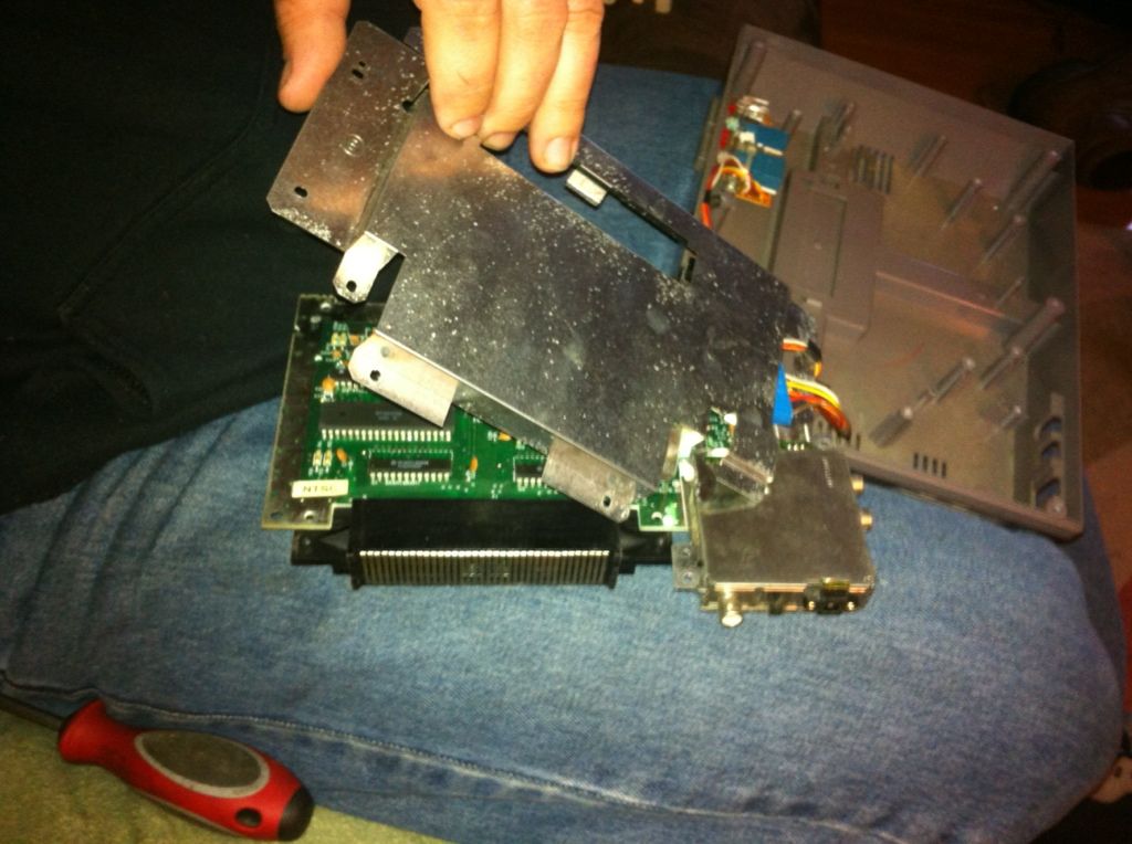
You can now lift up the board and flip it over. The lower RF shield can be seperated from the board without unplugging anything if you just move it properly but you can inplug the two connectors if its easier for you.
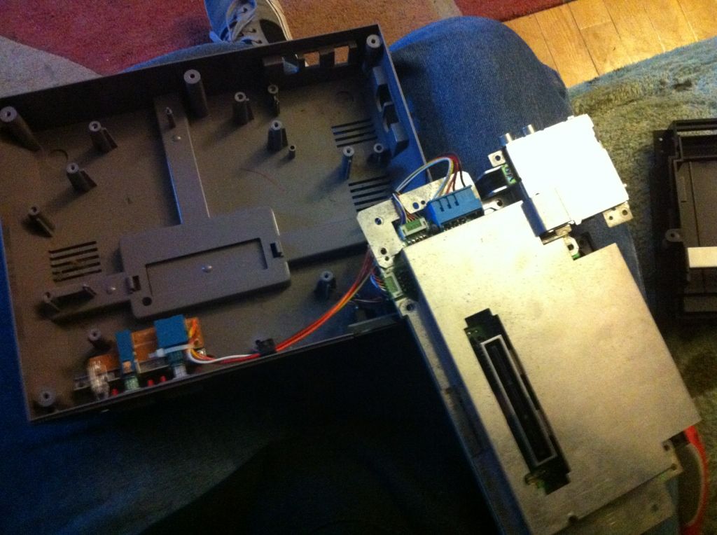
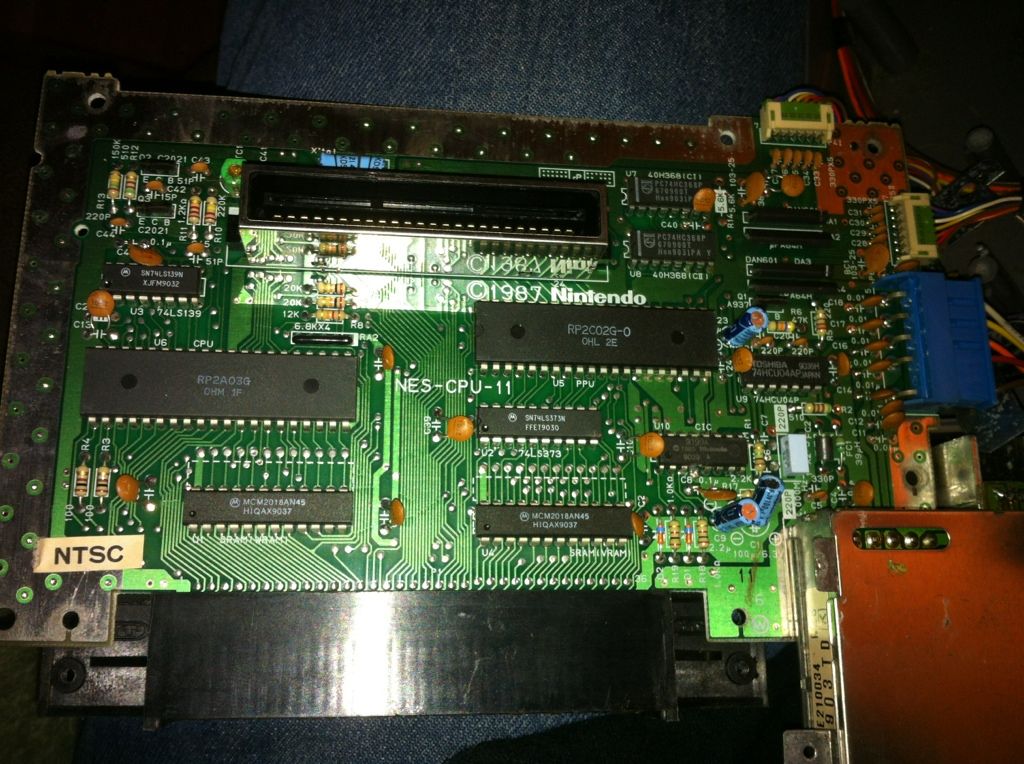
Now if you hold the board in the fashon I did. In the bottom right corner there is a chip above the two blue capacitors.
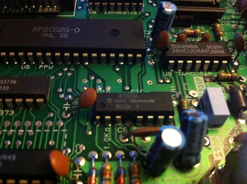
To disable the lockout feature of this chip you have to cut one connection. It is the fourth leg from the left on the bottom side of the chip. Use some small diagonal cutters.
Now put everything back how it was before you started screwing with it. Make sure when you put the tray back that you move it in a circular motion to get a piece on tha bottom feont of the tray under the board.
Enjoy no more flashing.

Lift the bottom half off and set the top half aside. Turn the buttom half over and dont lose the screws. Next remove the screws from around the RF shield. This will reveal the game tray.


I always remove the tray to make it easier for myself. Note that the two rear screws that hold the tray in are longer than all of the other screws that have been removed. Next remove the two screws in the corner where the a/c adaptor and rf switch plug in.
s1249.photobucket.com/albums/hh503/gamernes/?action=view¤t=E11E4C8B-A8A9-45E8-A4F8-6468905463F0-24660-00001931E2C382D3_zpsd6b586ee.jpg
You can now lift up the board and flip it over. The lower RF shield can be seperated from the board without unplugging anything if you just move it properly but you can inplug the two connectors if its easier for you.


Now if you hold the board in the fashon I did. In the bottom right corner there is a chip above the two blue capacitors.

To disable the lockout feature of this chip you have to cut one connection. It is the fourth leg from the left on the bottom side of the chip. Use some small diagonal cutters.

Now put everything back how it was before you started screwing with it. Make sure when you put the tray back that you move it in a circular motion to get a piece on tha bottom feont of the tray under the board.
Enjoy no more flashing.

